Design Optimisation using Computational Fluid Dynamics
Article by RINA Naval Architect
Article by RINA Naval Architect
23 May 2023
Owing to the increased adoption of numerical methods of analysis across industry, ship designers have access to more tools and techniques than before to aid in ship design. Rising fuel costs, carbon emissions targets and more challenging operational requirements are pressing ship designers to make efficient use of these tools to deliver optimal ship designs.
Designing a ship is a challenging engineering undertaking and requires a substantial level of technical expertise across multiple disciplines. The ship design spiral is a representation of the multiple stages of ship design - concept, preliminary, contract and detailed design.
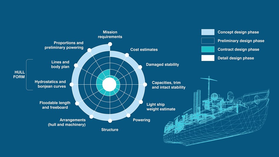
Whilst the ship design spiral appears suitable it can prove challenging to implement. Due to the expanding number of ship systems a growing number of analyses are needed. Following the ship design spiral can mean a detailed analysis is not performed for all systems on all designs.
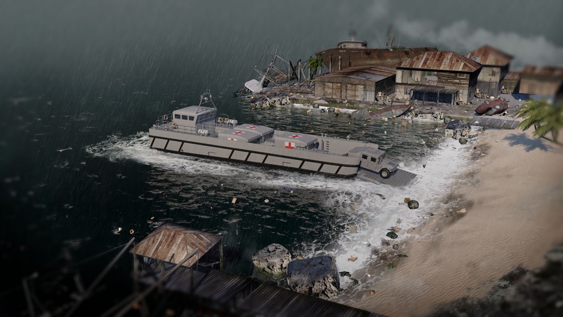
Recent ship design programmes illustrate fundamental changes in mission and performance requirements, necessitating ship designs which may be radically different from current ships in operation. One difficulty in designing such new concepts is the lack of experience from which to draw when performing design studies, landing craft are an example of this shift. Landing craft are increasingly required to be launched further offshore, making the hull form challenging to design as they need to:
Through simulation-based numerical methods ship designers can perform complex analyses more rapidly and at a reduced cost — enabling more efficient designs and facilitating progress through the ship design spiral. Numerical methods such as computational fluid dynamics (CFD) can establish many design parameters including main hull resistance, appendage drag, ship powering coefficients, air resistance, airflow and superstructure interaction, and gas emissions.
The CAIMEN landing craft — designed to support expeditionary operations worldwide, ranging from amphibious assault to disaster relief and humanitarian aid - is an example of the successful application of numerical methods of analysis. Using a CFD-based approach, BMT was able to de-risk and expedite the delivery of new landing craft designs to meet the operational requirements of modem-day navies.
CFD verification and validation
Verification and validation are the principal means for assessing the accuracy and reliability of CFD simulations. The objective of these tasks is to demonstrate the accuracy of the CFD code so it may be used with confidence and the results considered credible for design.
Verification is the assessment of the accuracy of the solution to a computational model by comparison with exact analytical results. When using a commercially available CFD software package — as is the case here — this validation is often performed by the software developer and documents made available for review and distribution.
Validation assessment determines if the CFD simulation agrees with physical reality through comparison to experimental results. To achieve this for the present case, CFD results were compared to results from towing tank experiments for the hull form design prior to the optimisation exercise. An extensive set of CFD simulations considered a range of loading conditions and operational conditions for which experimental results were available. Several computational meshes were considered to ensure the solutions conversed towards the exact solution as the mesh spacing was reduced. All resistance values obtained from the CFD simulations were within 1.496 of the experimental values — inside the total uncertainty of the experimental values. Providing confidence the CFD approach was able to capture the flow features affecting the landing craft.
Hull form optimisation
Confident the CFD approach was able to capture the flow features around the hull — the calm water resistance of the initial design of the hull was determined. This enabled a qualitative assessment of the key flow features negatively affecting the ship performance. Several iterations on the initial design were performed and a final design selected balancing the operational requirements of the landing craft and the hydrodynamic efficiency of the design. Results are presented for the initial design and the final design.
The Kelvin wake for the Initial hull form design shows to wave patterns, generated from the bow and the stern. The bow wave is pronounced and the wavelength shorter than expected for the design conditions. Due to flow separation at the bow, the bow wave does not interact strongly with the stern wave.
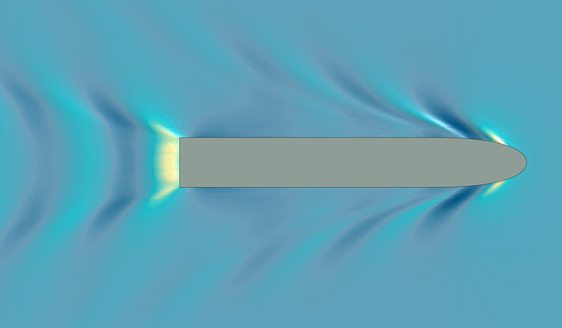
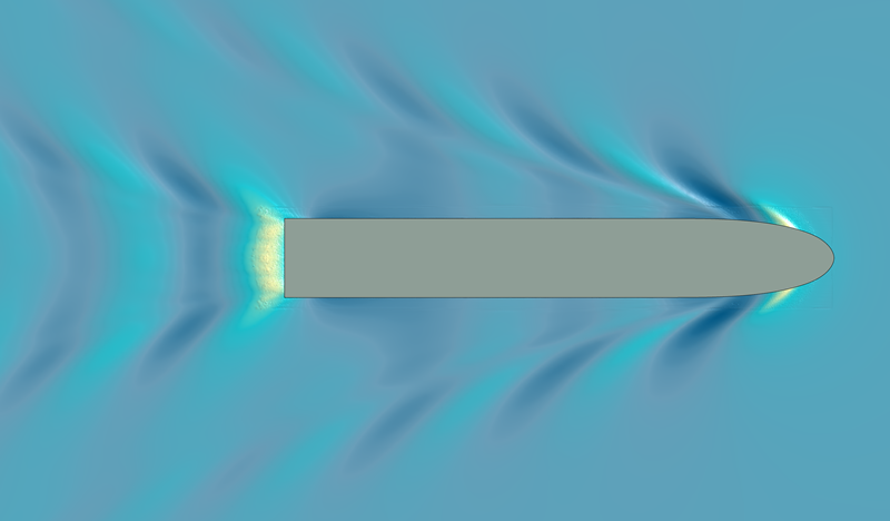
To assess the Kelvin wake further, a transverse profile of the free surface height was extracted a nominal distance away from the ship centreline.
At the bow, x/L = 1.0, the wavelength is significantly less than the theoretical wavelength, λ/L = 0.16, associated with the Froude number. This indicates a secondary wave pattern, a likely result of the sharp gradient in the hull close to the bow and the inflection behind the forward shoulder.
At the stern, x/L = 0.0, due to the far aft location of the centre of buoyancy for a ship operating at this Froude number a large wave pattern is generated. In addition, the waterline is not tapered in towards the stern creating a discontinuity. Both factors contribute to strong flow separation at the stern resulting in the formation of a significant wave pattern.
![]()
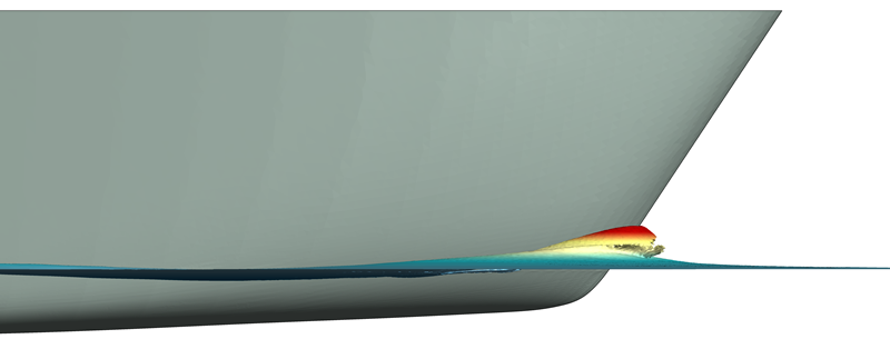
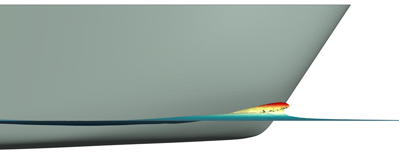
In the final design improvements were made to the fairing of the sectional area curves and the bow waterlines to reduce the secondary wave pattern which forms due to flow separation at the bow. This can be observed in the Kelvin wake and in the bow wave between the initial design and final design.
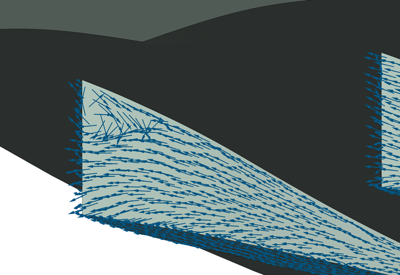
In addition to implementing design changes to minimise the wave resistance, the stern of the ship was a key focus area for optimisation. The design of the stern needs to balance the conflicting requirements of acceptable wake flow quality and speed performance. The propeller wake fraction for the initial design shows the propeller will operate in a spatially varying wake field, with changes in the axial velocity ranging from 45% to 95% of the freestream velocity.
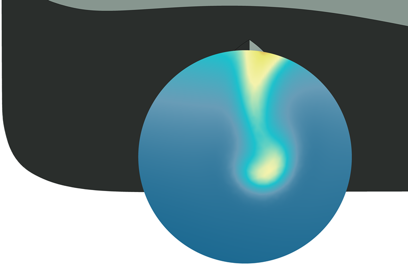
This wake fraction range is indicative of a vortex region at the aft end of the skeg — which can be seen in the flow vectors at the aft end of the skeg.
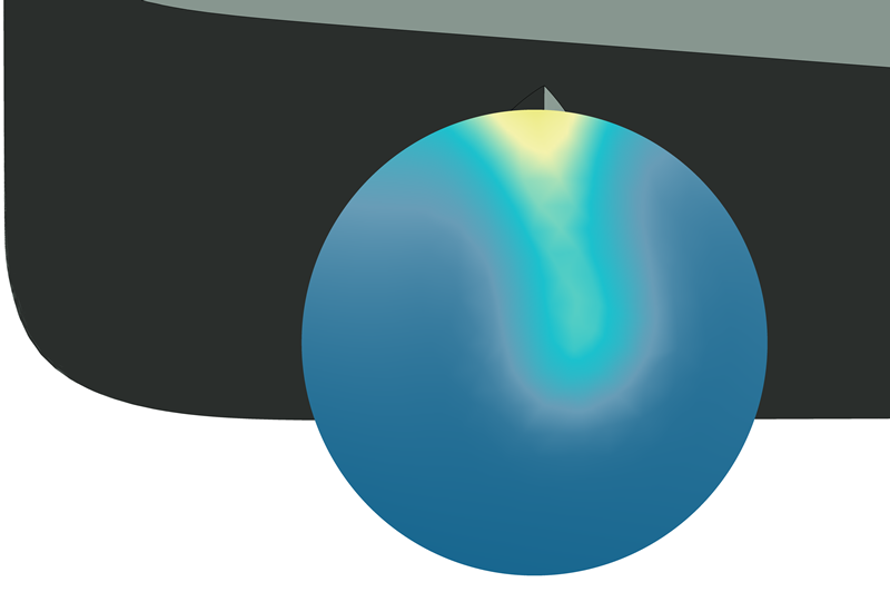
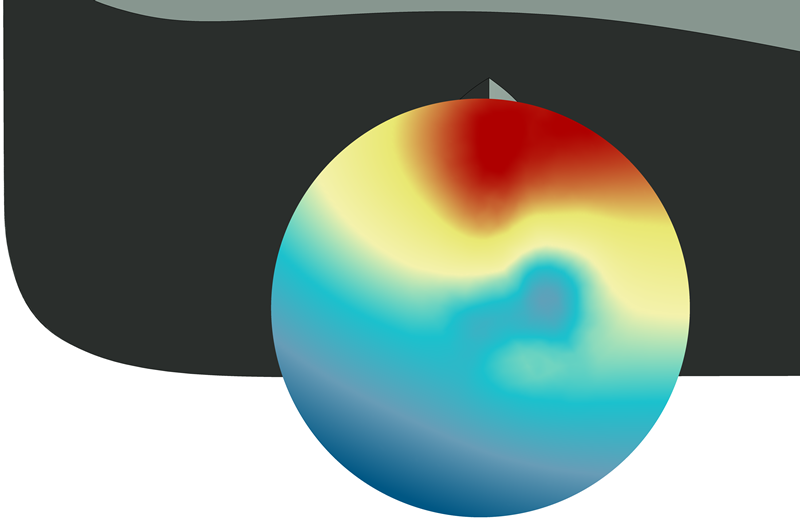
The large wake fraction range coupled with oblique flow into the propeller will adversely impact the propeller efficiency — increasing noise, vibration and cavitation levels. The vortex region at the aft end of the skeg can also be observed in the dynamic pressure field at the propeller, aiding in identifying the cause. Flow acceleration between the two skegs in the initial design causes a pressure differential on the two sides of the skeg, inducing flow over the trailing edge.
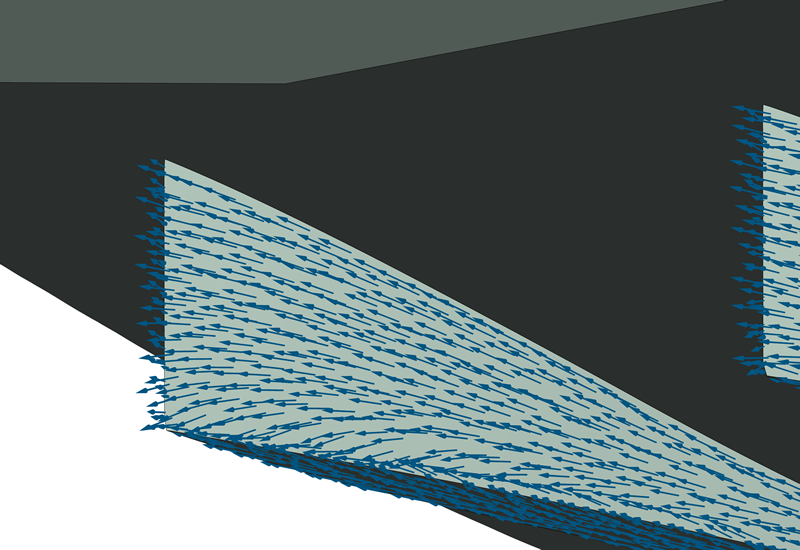
In the final design, an asymmetric design of the skeg reduced the size of the trailing vortex. Coupled with changes to the design of the propeller tunnels these changes removed the recirculation region at the aft end of the skeg — improving the propeller wake fraction and increasing the uniformity of the dynamic pressure at the propeller location.

In this study, a simulation based numerical approach was applied to the design and optimisation of a landing craft hull form. The initial design geometry was assessed through a CFD-based approach to identify areas where improvements may be made whilst retaining the operational requirements of the landing craft. Several design iterations were performed and a final design selected which achieved a balance between the operational requirement and hydrodynamic efficiency.
An assessment of the final design demonstrated a reduction in the wave height and reduced resistance — a reduction in the total hull resistance by 5%. In addition, significant improvements to the quality of the flow into the propeller results in notable improvements to the propulsive efficiency.
The study shows the capability for CFD-based optimisation approaches to form a fundamental part of ship design. Through employing panel codes based on strip theory, Navier-Stokes-based CFD approaches and towing tank testing, ship designers have access to a range of analysis approaches to achieve the right balance between time, cost, and fidelity of assessment throughout a ships design lifecycle.

Johnathan is a Chartered Engineer, Chartered Mathematician and Chartered Scientist with a background in Computational Fluid Dynamics and Mathematics. He has 15 years’ global experience delivering engineering consultancy services to the defence, energy, construction and process industries - working in countries in Europe, the Middle East, North America, South-East Asia and West Africa.
He is a Fellow of the Institution of Mechanical Engineers and a Fellow of the Institute of Mathematics and its Applications. As Analysis Delivery Group Lead at BMT he is responsible for a multidisciplinary team of consultants specialising in Computational Fluid Dynamics, data science and analytics, and model order reduction based solutions.

Chloe Yarrien
Maritime Autonomous Systems (MAS) are moving from concept to operational reality. Across defence and commercial maritime sectors, organisations are exploring how autonomy can improve operational effectiveness, increase persistence, reduce risk to personnel and enable new ways of working.

Panagiotis Kasionis
Coal cargoes remain a high-risk “routine” trade. Panagiotis Kasionis, explores key risks, regulatory changes and practical insights for managing exposure across the supply chain.

Dr Thomas Beard - UK / Europe
As shipping transitions to low‑carbon fuels, safety has become the defining challenge. This interview by RINA's The Naval Architect, explores how alternative fuels such as methanol, ammonia, hydrogen and LNG introduce new risks, and how smart vessel design, layered protection and crew competence are essential to delivering decarbonisation without compromising safety.

Thomas Hendrikx
When cargo operations go wrong, the true challenge often lies beyond the technical cause. In this thought leadership piece, Thomas Hendrikx explores how proactive remediation, from rapid fact‑finding to stabilising operations and aligning multiple stakeholders, protects time, money and reputation. He explains why the real value isn’t just solving the visible problem, but preventing the next one.