The Magnus Effect, a well spun yarn
Here, we explain the part that the Flettner Rotor has to play in the design of more efficient ships.
Here, we explain the part that the Flettner Rotor has to play in the design of more efficient ships.
Wind propulsion has been a popular research topic for green shipping enthusiasts throughout the 20th and 21st centuries, particularly at times of high bunker prices. The potential benefits are obvious; with the promise of reduced fuel consumption comes the possibility of improved profit margins, a reduced freight rate and a reduction in greenhouse gas emissions.
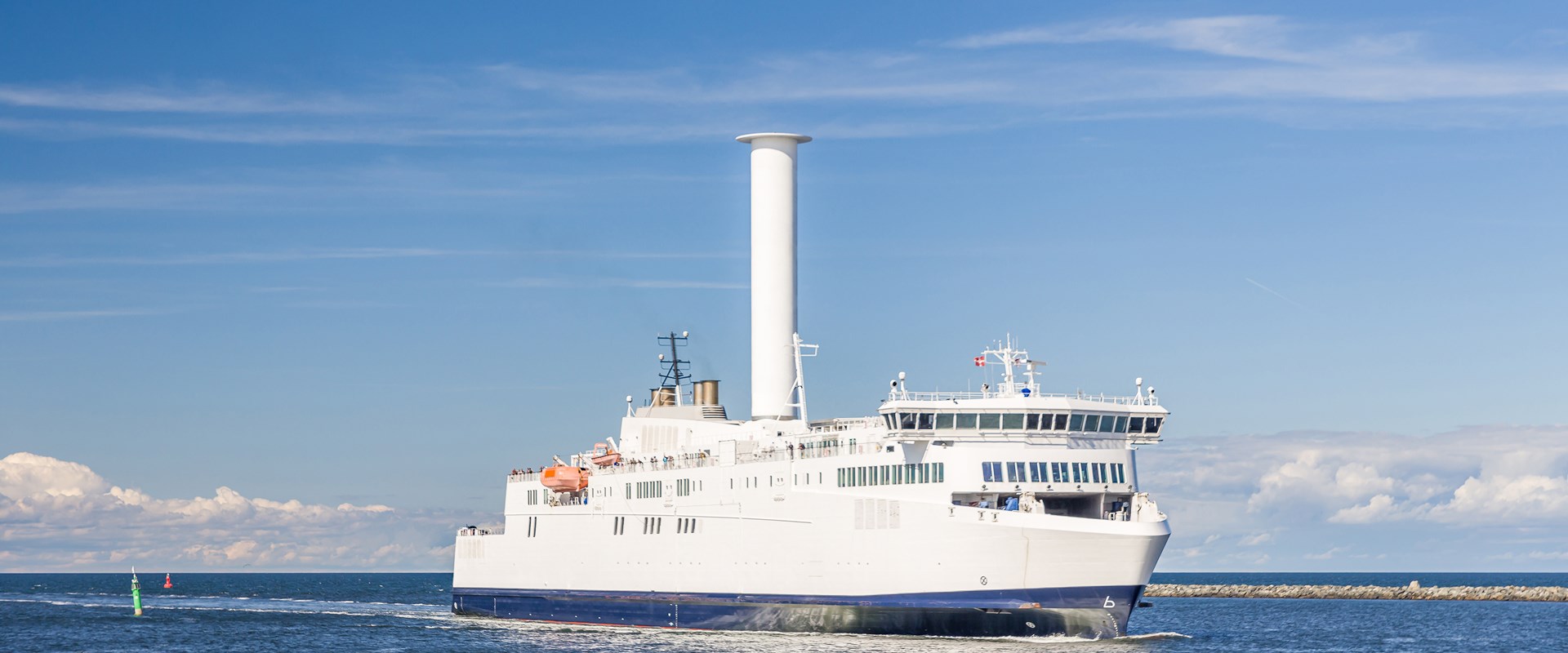
Flettner Rotors (FRs) are a form of wind based propulsion that utilises the ‘Magnus effect’, a phenomenon exhibited by a spinning body in a fluid flow incident upon it. It is this effect that is responsible for the curving flight path of a ball in many sports.
A FR typically comprises a cylinder with an endplate affixed to the top, mounted vertically to the deck of a ship. Through the action of a motor, the cylinder rotates in an air stream and a lift force is generated that can contribute to the propulsive needs of the ship.
FRs were first installed on a ship named Buckau in the 1920s, by a German scientist named Anton Flettner who realised their potential for ship propulsion. This installation was the proof of concept that allowed Buckauto sail across the Atlantic in 1926.
Although Buckau was successful in achieving its overall goal of saving fuel, the high capital cost alongside reduced bunker prices meant that ultimately the economics did not work and the rotors were taken out of commission. However, with the modern focus on energy efficient design and fuel saving technologies, matched with high bunker prices, the focus has once again come round to FRs and their potential to save ship owners money, as well as improve the green credentials of a ship.
There have been a number of previous studies that have modelled FRs and their benefits to shipping; however for the most part these do not consider ship fit factors and focus instead on potential savings over set wind routes. This study has sought to address this by creating a model that considers the limitations and locations of rotors on a ship, and makes only general assumptions about a ship’s voyage routing for a generic assessment of suitability for a given ship type.
Model approach
When planning an assessment for the potential retrofit of FRs on a ship, it must first be ensured that the candidate ship is architecturally well suited to accommodate them.
A candidate ship must be of a type that has an open area of deck, without extensive superstructure that would inhibit air flow, or deck gear/cranes whose operation may be obstructed by the FR. The FR imparts considerable forces to the structure of the ship so the mounting sites must be carefully chosen.
Certain ship types are unsuitable from the outset; Ro-Pax and container feeder type vessels lack the clear deck space required. For container vessels the installation would require the sacrifice of some container carrying capacity, besides the requirement for clear space around the rotor.
However, vessel types such as dry bulk carriers and tankers represent an ideal FR platform with their open deck, relatively slow steaming speeds, and favourable operating profiles which make them a more attractive proposition.
The ship selected to demonstrate the FR model is a chemical tanker of approximately 14,700 tonnes dead weight.
Rotor design
A ‘standard’ FR is a basic cylinder shape, with an end plate mounted at the top in order to improve the lift/drag ratio.
The only dynamically controllable variable of FRs is the rotational speed, which consequently affects the velocity ratio, defined as the ratio of the cylinder surface speed relative to the air speed. Over a limited range of speeds, the coefficients of lift and drag increase with the velocity ratio.
Our FR model was created within MatLab (software for numerical computation, visualisation, and programming), and performs all of the FR related calculations for a simulation and then feeds the results back into the ship model based on our proprietary marine power and propulsion tool.
Once the FR model has been run, the ship model assesses in detail how the ship’s power and propulsion systems respond to the reduction in resistance and the FR drive power demand.
Wind and forces
It is the apparent wind incidence upon the ship which is used for calculating the velocity ratio. The apparent wind varies in strength and direction for every combination of ship speed, true wind speed and true wind direction, thus the FR model takes all potential combinations into account.
It is assumed that the rotor is always rotated at the highest beneficial rotational speed; where that is not possible the rotors are turned off to minimise drag and power consumption. For a full 360degs azimuth the forces are averaged using a conservative approach to identify the effective FR thrust.
The power to drive the rotors is added to the ship’s electrical load, while the main engine power is reduced due to the lower apparent resistance. In the ship model, the main engine and diesel generators fuel demand is evaluated.
Negative effects
There are other factors that affect the overall FR performance:
• Increased heeling moment from sway forces
• Extra rudder drag from weather helm.
The sideways (sway) forces on the ship can become significant when the apparent wind angle is nearly dead ahead or astern. This large sideways force when combined with the vertical lever arm of a FR creates a heeling moment on the ship and will thus increase the angle of static heel. However, this was found to have a negligible effect (<1%) to performance, as the static heel does not exceed any roll angle normally experienced by the ship.
Another potential effect of large sway forces is the ability to create unbalanced yaw moments. This yaw moment must be countered by applying increased rudder angle (weather helm), which will increase drag and reduce the benefit from the FRs.
Power and savings
Figure 3 shows how the FR reduces the effective resistance seen by the propeller.
The benefit is most pronounced at lower ship speeds. This change in resistance translates into consistent fuel savings for all ship speeds as seen below in Figure 4.
With a generic operating profile, the ship used in this example stands to save up to 10% of its annual total fuel consumption with the installation of two FRs. There is good confidence in expecting better results after the application of wind routing and rotor throttling to obtain maximum aerodynamic efficiency.
Conclusions
The fuel-saving capability, carbon emission reduction potential and overall seaworthiness of FRs has been proven in several full scale installations to date, with positive results being reported as recently as 2013 with E-Ship 1. FRs represent an opportunity to improve the net efficiency of some ships, both when incorporated into new buildings and when retrofitted.
A FR model has been developed which allows a conservative assessment of the potential fuel saving benefits, demonstrates appreciable fuel savings, and considers some of the practicalities of their use.
Acknowledgements
This article represents work carried out by BMT, with the permission of the Energy Technology Institute’s Heavy Duty Vehicle (HDV) transport programme, whose support in the development of this technology model is gratefully acknowledged.
N/A
We address certain key topics that have been brought to our attention by our valued clients during their assessment of inspection reports.
James Calver
Our Naval Architects speak to RINA Ship and Boat International about how we can assist our clients early on with Future Fuels for their next vessel design.

Greg Fisk
Major Projects Lead and Senior Principal Consultant, Greg Fisk, discusses the growing need for sector-specific guidance for marinas and boat yards, in-light of increasing regulation to decarbonise industries.

Brad Saunders
Brad Saunders, our Senior Principal Engineer & Technical Lead for APAC, Coastal & Maritime Engineering, sets out how for small ports a modern approach to asset valuation is appropriate and holds considerable potential to uncover hidden value.